DigitalOcean Load Balancer: Scaling to 1,000,000+ Connections
DigitalOcean’s managed load balancer product allows customers to route traffic to Droplets and DigitalOcean Kubernetes nodes hosting their application, enabling them to easily improve the scalability and performance of their infrastructure. In this post, we’ll walk through the steps we took to scale the DO Load Balancer to 1,000,000+ connections over the past few years.
DO-LB past implementation from 2018
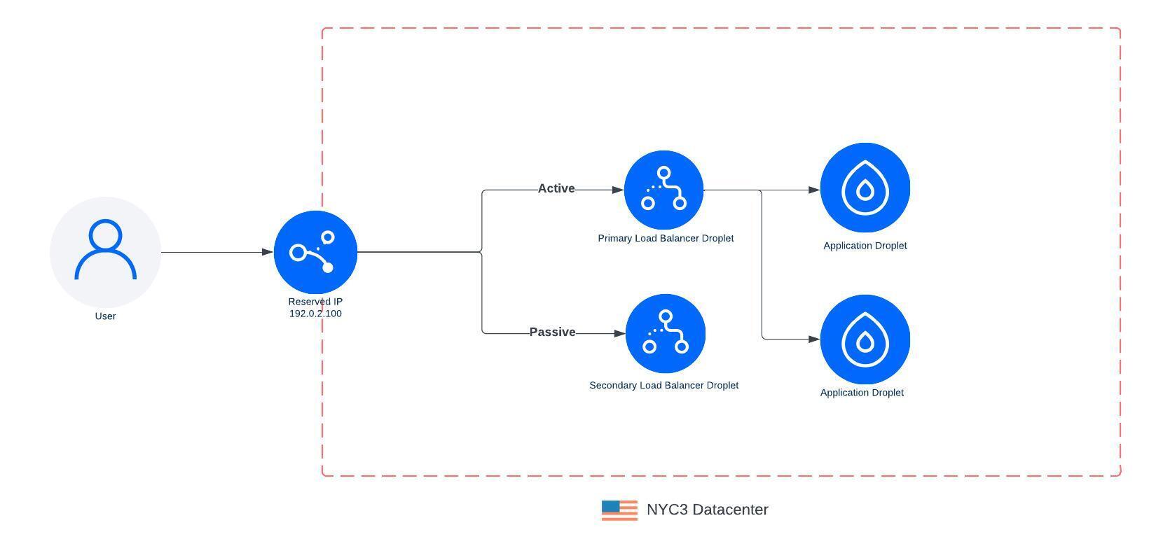
The original LoadBalancer (LB) architecture (from 2018) was deployed using a Droplet, which we call a load balancer Droplet. We attached a reserved IP to the load balancer Droplet to support failing over to another Droplet if the primary became unhealthy. This allowed us to perform upgrades to the LB by spinning up a new LB Droplet with the updated software and then switching traffic over once it is ready. The downside with this approach was that during the period that we switch LB Droplets, all existing connections would be dropped and clients needed to reestablish a connection to the load balancer.

Over time we heard from our customers that they needed to scale higher with more connections or more throughput. We launched a resizable load balancer with S/M/L t-shirt sizes and scaled the LB Droplet vertically in 2020. The original Load Balancer product was based on a 1 vCPU Droplet, and the medium and large were based on a 2 CPU and 4 CPU Droplet. These larger sizes enabled the medium- and large-sized Load Balancers to handle larger workloads, allowing customers to route more traffic through their LB and scale up their workloads. We knew this wouldn’t resolve all customers’ needs but it was an initial milestone on our journey to scale to higher and higher workloads.
During the design of our next iteration, which started in 2021, there were a number of goals we wanted to meet, including:
-
Scale to 1,000,000+ connections
-
High Availability—Ensuring the LB doesn’t go down when a single LB droplet becomes unavailable
-
Keep pricing simple
We wanted customers to be able to scale their load balancing layer but have a fixed price so they would know what their bill would be at the end of the month.
Exploring our options
We considered moving to a Kubernetes-based solution deployed onto bare metal but that posed many challenges.
-
Our deployment was large enough that we would need to deploy and manage many independent clusters within each data center. Our team would need to manage noisy neighbor problems and many of the complexities of managing multi-tenant compute. Other teams at DigitalOcean managed this for us already, so we didn’t want to duplicate that effort or want to take ownership of this problem.
-
The path between the LB Droplet and customer Droplet happens over their VPC network, and we got this for free since LB Droplets reside within the customer’s VPC. We would need to build a new VPC datapath from this bare metal Kubernetes cluster to enable connectivity to customer Droplets. Each pod would need to have a leg into the VPC and it would make the pod lifecycle quite complex. We would need to allocate an IP from the VPC for each pod, it would need to be added/removed from the VPC to form the VPC mesh, and we would need to support the tunneling of VPC traffic to and from the pod. All of this orchestration would need to happen when pods spin up and down.
We ultimately scrapped the plan to use Kubernetes and pivoted to a solution that kept the LB Droplet layer. This eliminated a large amount of scope while continuing to meet our initial design goals. We accomplished this by adding an additional tier to our load balancer architecture. This new tier leveraged a passthrough network load balancer (NLB) that we deployed onto bare metal. Although we needed to deploy a bare metal tier similar to the Kubernetes solution, we needed significantly less compute to power this layer vs moving the entire L4/L7 workload. The compute needs of an NLB are orders of magnitude less than an HTTP load balancer which needs to terminate the TCP connection, perform TLS handshakes, process HTTP headers, and more. We also didn’t need to build and manage a new VPC datapath since we would still have LB Droplets.
DigitalOcean Load Balancer current implementation
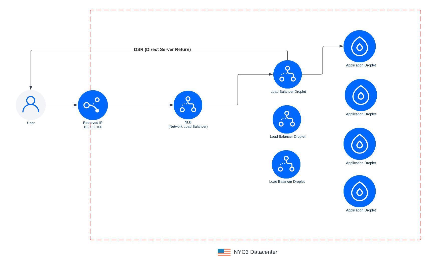
On the NLB, we leveraged BGP (Border Gateway Protocol) and ECMP (Equal-Cost-Multipath) to spread traffic across N number of servers deployed into each DC. We also leveraged an OSS project, Katran, which allows us to route connections to one or many load balancer Droplets in an active-active architecture.
BGP is a protocol that allows us to configure our network fabric on where traffic should be routed to within the data center. ECMP is a feature of BGP that allows us to spread traffic across many individual servers. This turns each Load Balancer IP into an anycast IP within the DC network fabric. Depending on where connections are coming from, the network fabric will hash the 5 tuple (src IP, src port, dst IP, dst port, protocol) to choose the closest server to route to. Each server is deployed into a rack and connects to the ToR in its rack and a ToR in a sister rack. This ensures redundancy if a ToR fails or needs to be taken down for maintenance. We can also tolerate one or more individual servers failing with traffic automatically routing to other healthy servers.
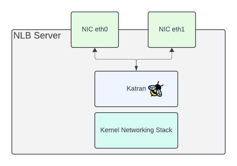
Diving into each of these bare-metal servers, this is where we run Katran, an eBPF program. This is an XDP (express Data Path) program that sits between the path of the NIC (network card) and the kernel networking stack. This allows for packet processing to be done directly off the NIC which enables a highly performant load balancing data path. Our synthetic tests and real world traffic show we can saturate a 50Gbps NIC with little CPU usage. The NIC itself is the bottleneck on each of our servers.

Katran is based on Maglev, a paper released by Google and has become ubiquitous throughout the industry. Katran is based on a connection table and/or a consistent hash of each packet. As packets flow through the server, the connection table is used to determine which backend to route each packet to. If there isn’t an entry in the table, Katran will perform a consistent hash on the packet to pick a new backend. An entry is then added into the table so future packets can be routed to the same backend. Changes to the network fabric can cause existing flows to be routed to entirely different NLB servers, this can happen for any number of reasons such as adding/removing NLB servers, either to add new capacity or take out during maintenance. During these events, we will rely on the consistent hash of the packets to ensure stable routing even though flows are being rerouted to new NLB servers. We take precautions to ensure that LB Droplet maintenance and NLB server maintenance events don’t overlap which has the highest potential to cause connection resets.
With the new NLB architecture now in place, we migrated all customers’ load balancer to this new data path and now route all traffic through it. The NLB will load balance TCP/UDP connections to one of the load balancer Droplets. The LB Droplet will terminate the connection and then load balance traffic to the customer’s application Droplet over its VPC. We also leverage DSR (Direct Server Return) so all egress traffic leaves the LB Droplet and goes directly back to the client. This reduces the load on the NLB layer which only needs to scale to the size of the ingress traffic which is typically quite less than egress traffic.
This also enables us to scale LB Droplets up / down, rotate LB Droplets during maintenance events such as software upgrades, and shift traffic over to new LB Droplets. We can also now gracefully drain connections from old LB Droplets before shutting them down.

With the change to NetLB, we replaced S/M/L sizes with size units which allows customers to scale from 1-200 nodes. Each node can handle up to 10,000 connections and/or 10,000 req/sec. Scaling from 1-200 nodes takes a few minutes but allows you to scale from 10,000 connections to 2 million connections. Each node also acts as a form of redundancy, so adding more nodes increases your load balancers availability. Below is an example of a load balancer running in production serving real customer traffic using this new architecture with connections peaking nearly a million.

Our goal was to ensure a consistent product experience as we evolved the architecture to enable increased scale. This enabled us to automatically transition customer load balancers to the new architecture without any downtime or any painful migration required on the customer’s end. We had predictable pricing as customers scaled their load balancers and allowed customers to choose the level of redundancy by choosing the number of nodes.
The Load Balancer product architecture has evolved throughout years since it was released first. It scaled from 10K connections and 10K RPS to 2 million connections and up to 2 million RPS. We continue working on new features and performance improvements to satisfy the high performance and high availability requirements of our users’ deployments.
We look forward to customers trying out the improved Load Balancer product, and hope you found this write-up of our process to get to 1,000,00+ connections and increased availability interesting!
Additional resources:
Related Articles

Managing Your Cloud Security Posture on DigitalOcean
Tyler Healy and Asif Wani
July 24, 2024•4 min read

GPU Droplets, HIPAA Covered Products, and more updates from DigitalOcean Deploy
July 17, 2024•4 min read
